HeltecTM ESP32+LoRa Series Frequently Asked Questions
This page contains the most frequently questions from user. If this page’s detail can’t solve your problem, you can also talk in our forum: community.heltec.cn
Can’t Download Firmware
Use a better USB cable, or change a USB socket;
Check and make sure the CP210x drive had been correctly installed, users can refer to this document: Establish Serial Connection;
Press “PRG” button before upload.
Orange LED Blink Problem
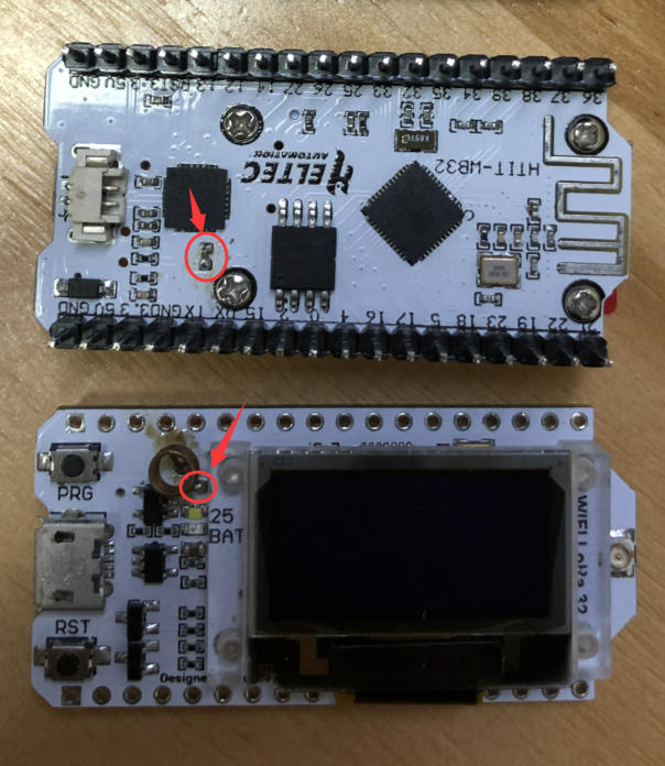
Annoying orange LED lights are always flashing? It’s because the battery management chip MCP73831. with the following control logic:
Blink – Power on
Light – Charging
Turn OFF – Battery filled
Change this capacitor to 220nF to temporarily correct this problem.

We had use the TP4054 to replace MCP73831, the orange LED have new control logic:
Dim – Power on
Light – Charging
Turn OFF – Battery filled
Another Communication Bus Usage Example
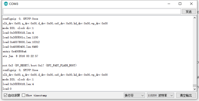
System Reset All the Time

According to the situation we have collected so far, the most likely to cause a constant reset problem may have two reasons:
Power supply problem: please make sure the voltage of USB ≥ 4.7V, 300mA;
You chose an error board: because each type of board may have a different FLASH size, and they have a different partition map, it will cause the internal logic error.
About WiFi LoRa 32(V2) Sleep Current Test
Use the battery to power the development board, and connect an ammeter to the positive pole of the battery. Download this Example Code
This video is the test effect:Test Video
Node to node communication
On the premise of no hardware problem, LoRa nodes can communicate with each other node-to-node. The key to success node-to-node communication need make sure the following 7 points the same:
The same sending and listening frequency:
LoRa.setFrequency(frequency);The same bandwidth:
LoRa.setSignalBandwidth(signalBandwidth);The same coding rate:
LoRa.setCodingRate4(codingRateDenominator);The same preamble length:
LoRa.setPreambleLength(preambleLength);The same sync word:
LoRa.setSyncWord(syncWord);The status of
LORA_IQ_INVERSIONis the same;the same
SPREADING FACTOR;
Know more information about LoRa node-to-node communication, please refer to LoRa basic library APIs: https://github.com/HelTecAutomation/Heltec_ESP32/blob/master/src/lora/API.md
Vext control
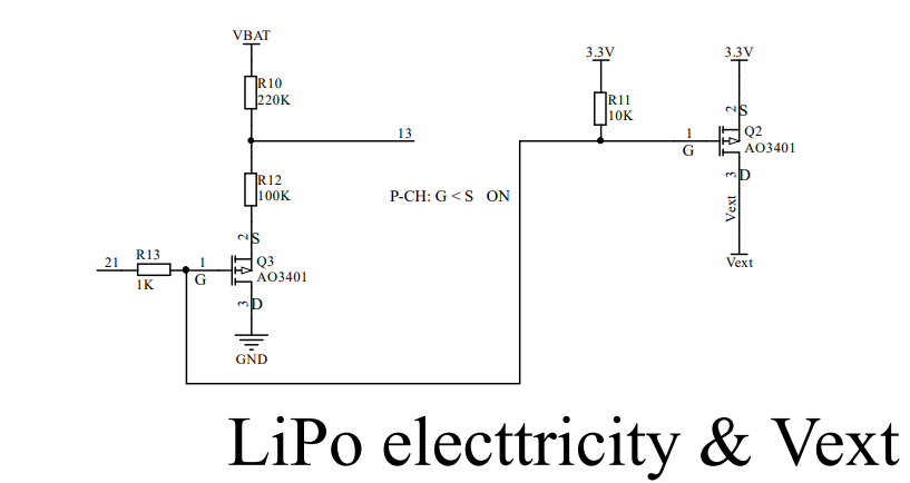
The Vext is a power source for external devices. Refer from the schematic diagram, It’s controlled by GPIO21:
GPIO 21 --> LOW --> Vext(3.3V/250mA) ON
GPIO 21 --> HIGH --> Vext(3.3V/250mA) OFF
