LoRaWAN
HRI-4851L is a DTU device using LoRaWAN protocol, and its network access must also rely on LoRaWAN gateway and server.
Hardware Connection
As shown in the figure,Connect the power wires and data bus of the device.
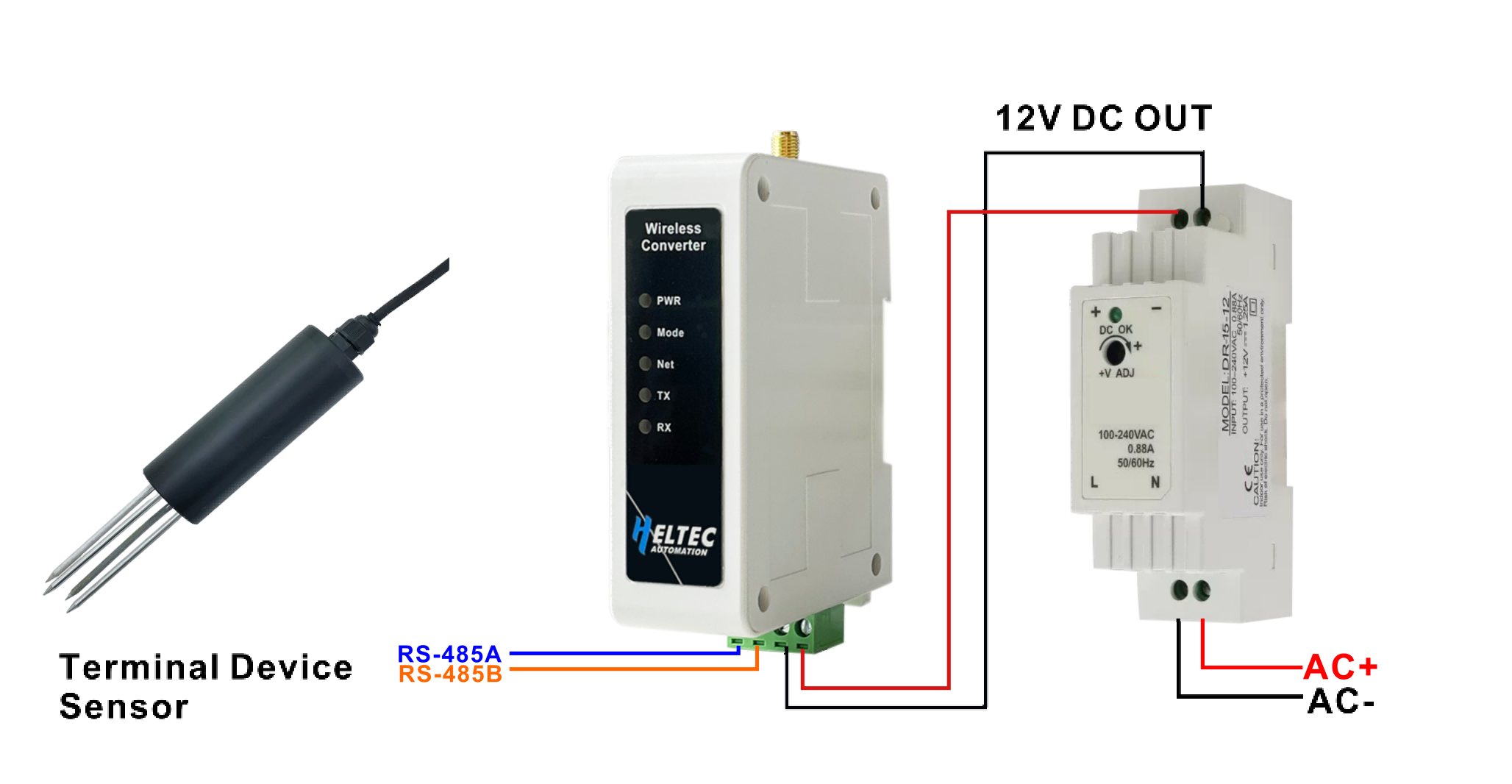
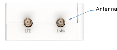
Install the antenna we provided.
Enter Configuration Page
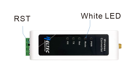
Press the RST button, until the white LED flashed quickly, at which point the device enters the configuration mode.
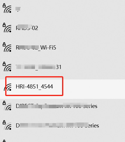
In configuration mode (White LED flashed quickly), you can find HRI-485x’s Wi-Fi, in general, it has the format”HRI-4851L-xxxx”, connect to this WiFi.
Enter 192.168.4.1 through the browser.

Parameter specification
Configure the parameters according to your needs.
REGIONLoRaWAN frequency plan, needs to be set same on nodes, gateways, and servers.ClassLoRaWAN class capabilities, needs to be set same on nodes, and servers.OTAA/ABPActivation mode, needs to be set same on nodes, and servers.ADRLoRaWAN data rate adaptation, whenAdris on, the DR Option is the DR Used for network access request; whenADRis off, the DR Is the DR For network access and uplink data.The default port of uplink and downlink is 2;
The power is adaptively determined by the
ADRwhen theADRis on;ConfirmData received acknowledgment.485 BaudRS-485 data baud rate, needs to be same as terminal device.DEVEUIAPPEUIAPPKEYIdentifiers for your LoRaWAN device, These identifiers will be used when you register the device on the server.ChannelThe channel of LoRaWAN, the channel of the node needs to be included by the channel of the gateway. Performs multiple channel Settings, separated by whitespace, such as “0-2 5 10-17”.INTERVALRS-485 query instruction cycles in seconds.RETRYNumber of retransmission attempts.PRODUCTProduct model.FIRMWAREFirmware version.
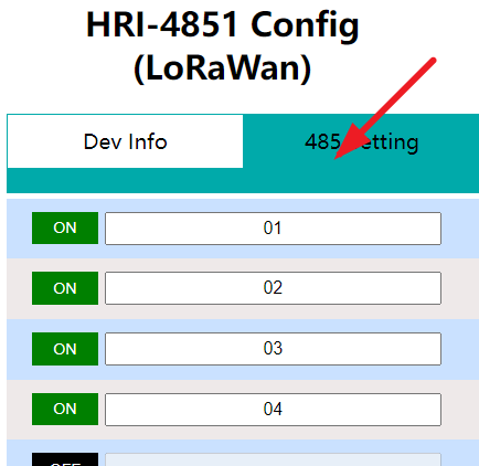
RS-485 Setting
Each RS-485 instruction supports up to 32bytes, and if multiple 485 instructions are enabled, the interval between each two instructions is 5S.
After the configuration is completed, click submit, press the RST when the white LED is always on, and the device enters the working state.
Connect to LoRa Servers
The default downlink port is 2.
Connect to TTN/TTS
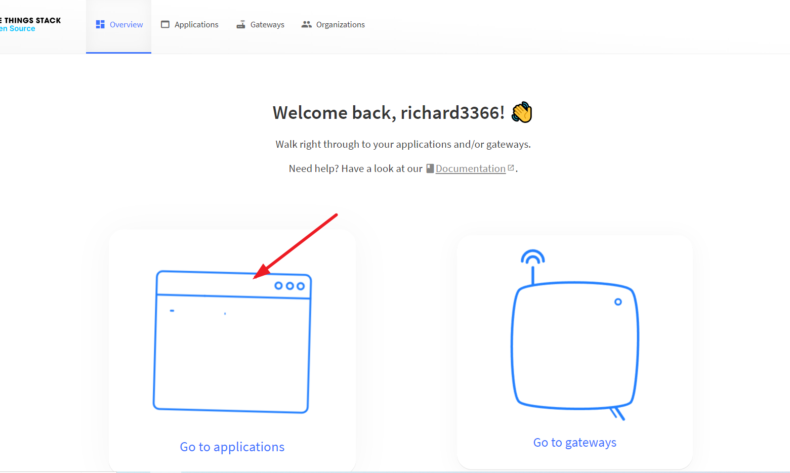
Before that, make sure there is a LoRa Gateway active in your TTN/TTS account.
Log in to your TTN/TTS account and click the icon shown by the arrow.
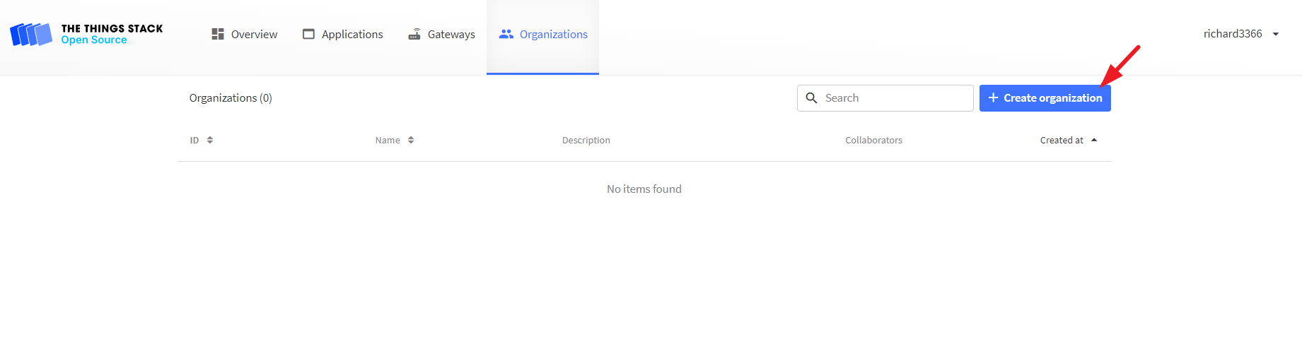
Click
Create Organizationto create an Application.
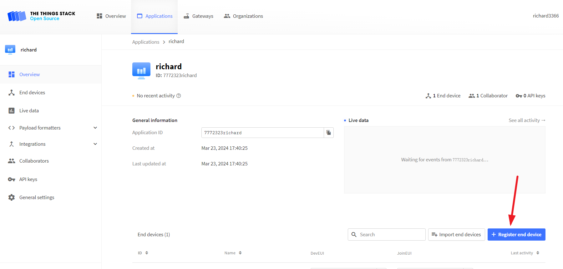
Click
Register end device.
Click
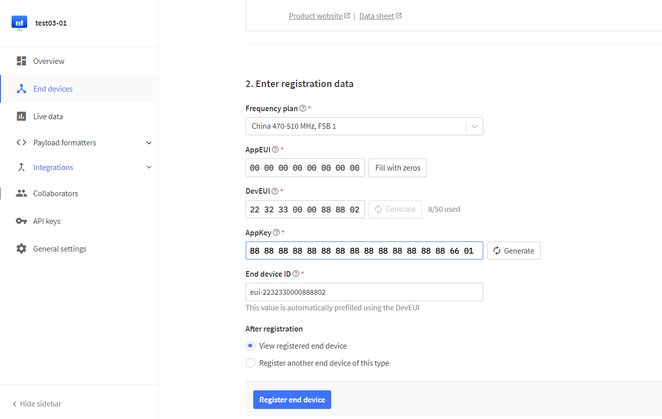
Enter end device specifics manually, The following options will pop up:
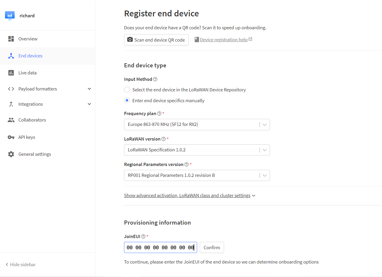
Freq planSelect the frequency band corresponding to the device.LoRaWAN versionChoose ‘LoRaWAN Specification 1.0.2’.Regional Parameters versionChoose ‘RP001 Regional Parameters 1.0.2 revision B’.
Note
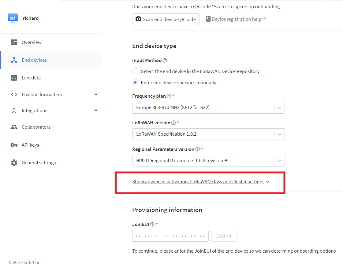
On server, the default mode is OTAA and CLASS_A, if you need to change this mode, please open the options below.
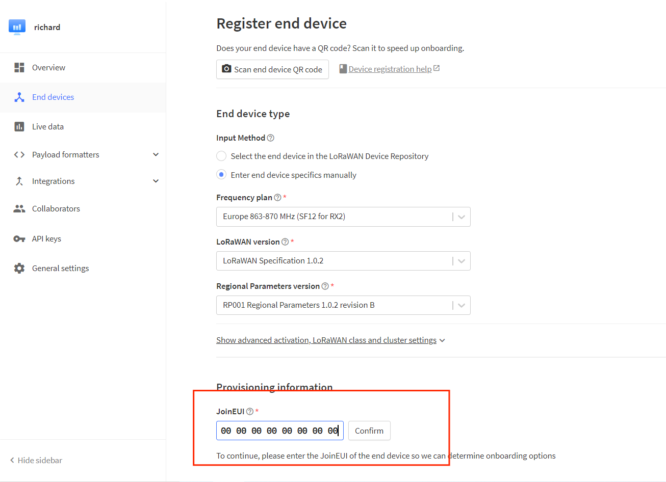
Fill in
joinEUIand click Confirm.
Note
The joinEui is represented as AppEui on the device configuration page.
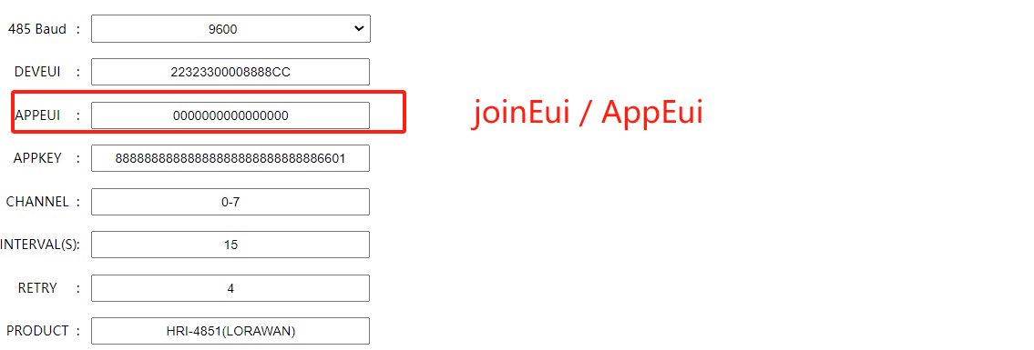
Refer to the configuration page, fill in the
DEVEUIandAPPKEY, clickRegister end device.
After registration is complete, if all is well, you will see the device active.
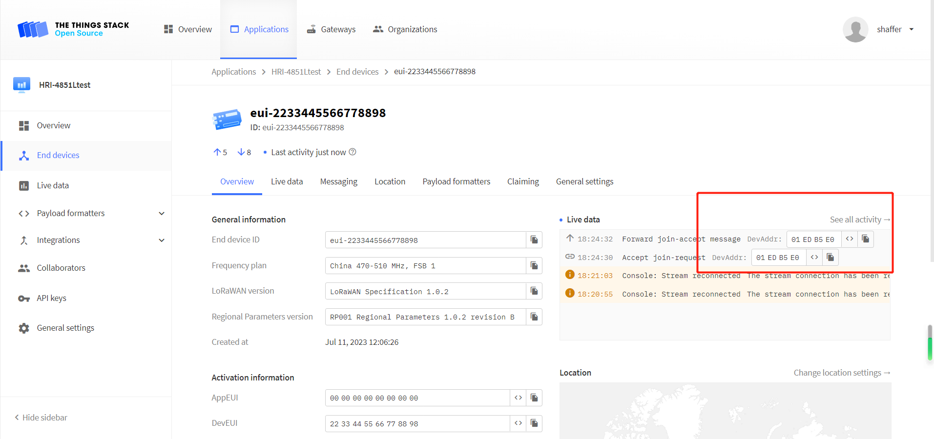
Give instructions. Click the
Messagingoption, selectFport 2,Bytes, and enter the downlink command.
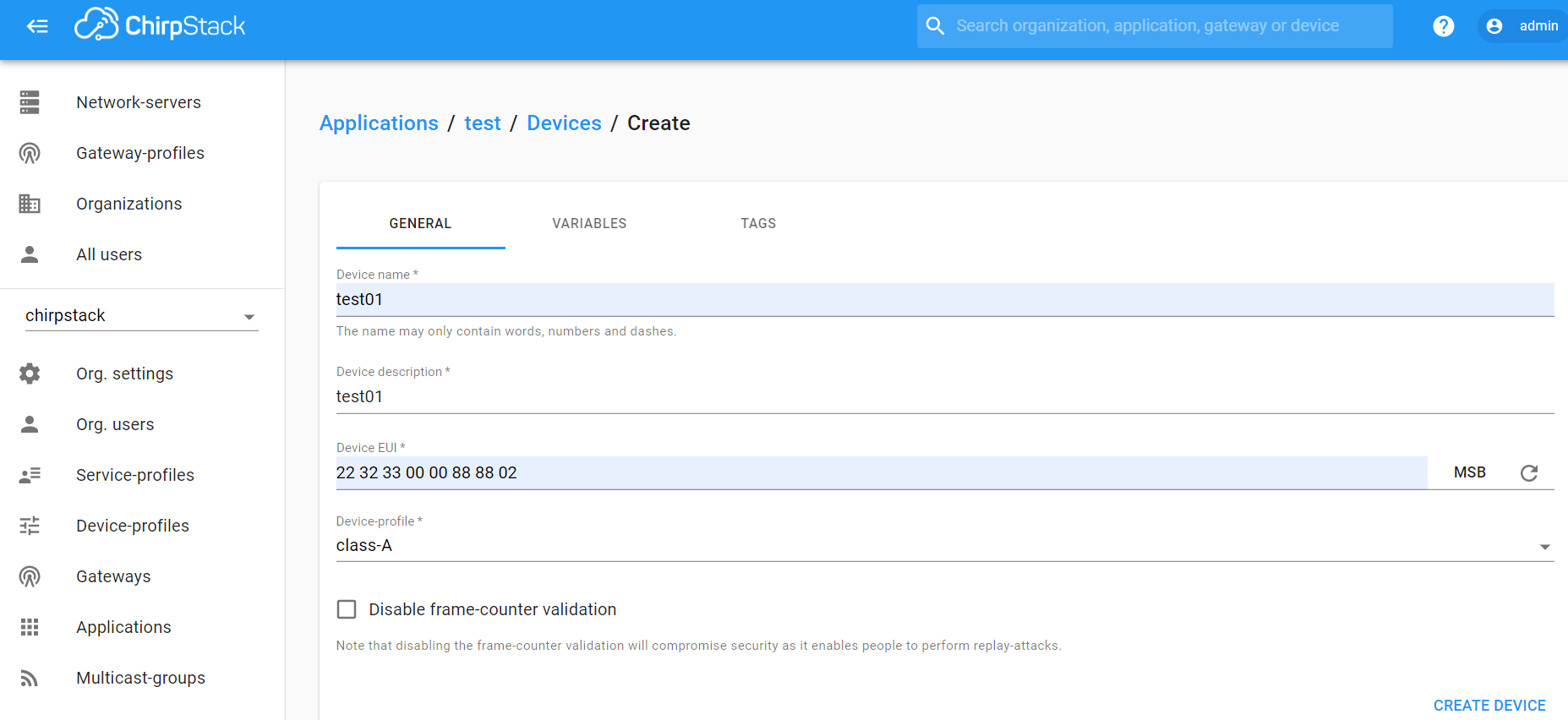
Connect to ChirpStack
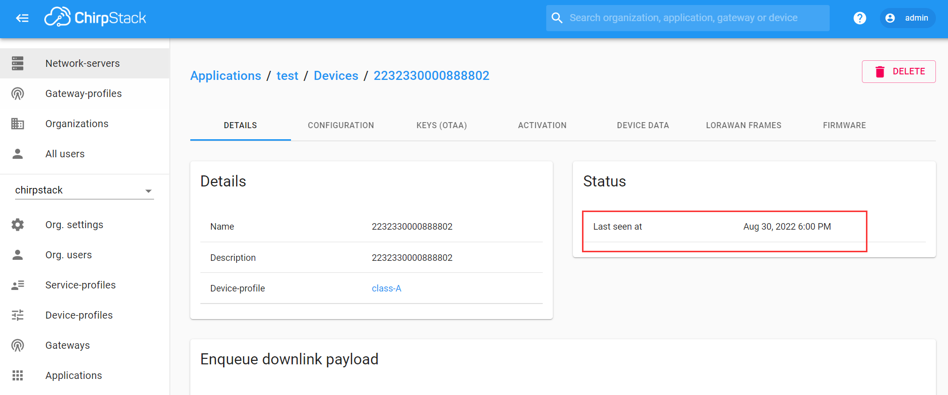
Register a new device in ChirpStack’s “Applications” page. Enter the device name, description, DevEUI. Select Device-profile.
Enter the Application key of the device.
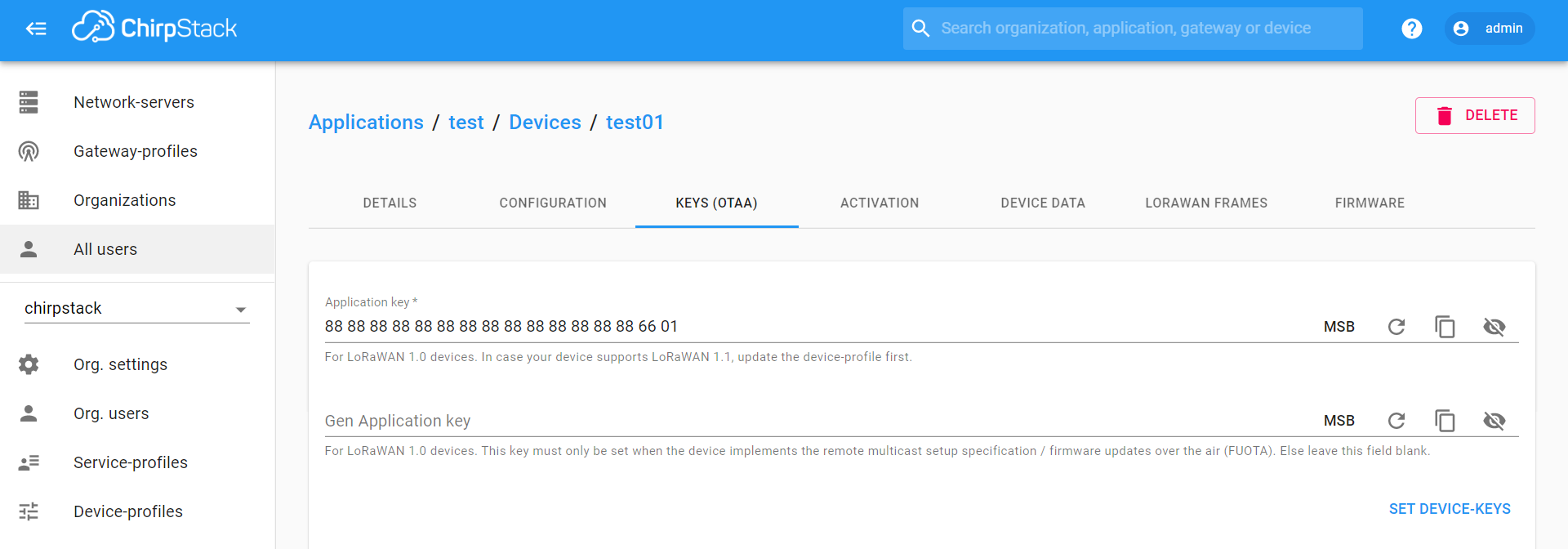
After registration is complete, if all is well, you will see the device active.
Important Hints
Please double check the following two things:
The LoRaWAN parameters are the same as server!
The listening frequency of your LoRa Gateway is the same as ESP32 LoRa node’s sending frequency. We strictly follow LoRaWAN™ 1.0.2 Regional Parameters rB;